当前课程知识点:数字逻辑电路 > Chapter8 Generation and Shaping of Pulse Signal > Test8 > Chapter3 Logic Gates
Chapter3 Logic Gates
本章导读
在数字电路中,所谓“门”就是只能实现基本逻辑关系的电路。最基本的逻辑关系是与、或、非,最基本的逻辑门是与门、或门和非门。逻辑门是在集成电路上的基本组件。简单的逻辑门可由晶体管组成。这些晶体管的组合可以使代表两种信号的高低电平在通过它们之后产生高电平或者低电平的信号。高、低电平可以分别代表逻辑上的“真”与“假”或二进制当中的1和0,从而实现逻辑运算。常见的逻辑门包括“与”,“或”,“非”即 “反相器”等。
与门
与门(英语:AND gate)是数字逻辑中实现逻辑与的逻辑门。仅当输入均为高电压(1)时,输出才为高电压(1);若输入中至多有一个高电压时,则输出为低电压。
或门
或门(英语:OR gate)是数字逻辑中实现逻辑或的逻辑门。只要两个输入中至少有一个为高电平(1),则输出为高电平(1);若两个输入均为低电平(0),输出才为低电平(0)。
反相器
反相器(英语:Inverter)也称非门(英语:NOT gate),是数字逻辑中实现逻辑非的逻辑门。
本章要点
3–1 The Inverter
3–2 The AND Gate
3–3 The OR Gate
3–4 The NAND Gate
3–5 The NOR Gate
3–6 The Exclusive-OR
3–7 Exclusive-NOR Gates
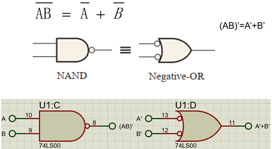
图1 与非门等效的符号及其运算
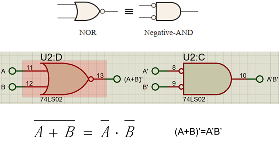
图2或非门等效的符号及其运算
-1.1 Structure and Methods
-1.2 Introductory
-Chapter1 Introductory Concepts
-Test1
-2.1 Number Systems
-2.2 Codes
-Chapter2 Number systems and Codes
-Test2
-3.1 Logic Gates(1)
-3.2 Logic Gates(2)
-Test3
-4.1 Boolean Algebra
-4.2 Logic Simplification
-Chapter4 Boolean Algebra and Logic Simplification
-Test4
-5.1 Analysis of combination logic circuit
--5-1 Analysis of combination logic circuit
-5.2 Design of combination logic circuit
--5-2 Design of combination logic circuit
-5.3 Half and Full Adders
-5.4 Encoders
-5.5.1 Decoders(1)
-5.5.2 Decoders(2)
-5.5.3 Decoders(3)
-5.5.4 Decoders(4)
-5.6.1 Multiplexers (Data Selectors)(1)
--5-6 Multiplexers (Data Selectors)(1)
-5.6.2 Multiplexers (Data Selectors)(2)
--5-6 Multiplexers (Data Selectors)(2)
-5.7 Comparators
-Chapter5 Combinational Logic Circuit
-Test5
-6.1 Latches
-6.2 Flip-Flops
-6.3 Flip-Flops Applications
-Test6
-7.1 Analysis of Sequential logic circuit-1
--7–1 Analysis of Sequential logic circuit-1
-7.2 Analysis of Sequential logic circuit-2
--7–2 Analysis of Sequential logic circuit-2
-7.3 Design of Sequential logic circuit-1
--7.3 Design of Sequential logic circuit-1
-7.4 Design of Sequential logic circuit-2
--7-4 Design of Sequential logic circuit-2
-7.5 Counters-1
-7.6 Counters-2
-7.7 Registers-1
-7.8 Registers-2
-Chapter7 Sequential Logic Circuit
-Test7
-8.1 555 Timer circuit structure and working principle
--8.1 555 Timer circuit structure and working principle
-8.2 Application circuit of 555 Timer
--8.2 Application circuit of 555 Timer
-Chapter8 Generation and Shaping of Pulse Signal
-Test8