当前课程知识点:数字逻辑电路 > Chapter8 Generation and Shaping of Pulse Signal > Test8 > Chapter1 Introductory Concepts
本章导读
数字逻辑电路广泛应用于各种领域。如计算机、电视、通信系统、雷达、导航和制导等应用系统,军事系统,医疗仪器工业过程控制和消费电子使用数字技术。数字技术已经从真空管电路发展而来到分立晶体管到复杂的集成电路,其中许多包含数以百万计的晶体管其中许多是可编程的。
模拟量是具有连续值的量。数字量是具有一组离散值的量。大多数可以定量测量的事物在自然界中以模拟的形式出现。模拟量的例子有时间、压力、距离和声音。
数字和模拟电子学都用于各种机械系统的控制。由机械和电子元件组成的跨学科领域被称为机电一体化。机电系统广泛应用于家庭、工业和交通运输领域。大多数家用电器由机械和电子元件组成。电子设备通过水流、温度和循环方式来控制洗衣机的运行。制造业在过程控制和装配方面严重依赖机电一体化。
用来表示1和0的电压称为逻辑电平。理想情况下,一个电压电平表示高,另一个电压电平表示低。然而,在实际的数字电路中,高电压可以是在规定的最小值和规定的最大值之间的任何电压。同样地,低电压可以是在规定的最小值和规定的最大值之间的任何电压。在接受的高水平范围和接受的低水平范围之间不能有重叠。
Fixed-function digital ICs are classified according to their complexity. They are listed here from the least complex to the most complex. The complexity figures stated here for SSI,MSI, LSI, VLSI, and ULSI are generally accepted, but definitions may vary from one source to another.
Small-scale integration (SSI) describes fixed-function ICs that have up to ten equivalent gate circuits on a single chip, and they include basic gates and flip-flops.
Medium-scale integration (MSI) describes integrated circuits that have from 10 to 100 equivalent gates on a chip. They include logic functions such as encoders, decoders,counters, registers, multiplexers, arithmetic circuits, small memories, and others.
Large-scale integration (LSI) is a classification of ICs with complexities of from more than 100 to 10,000 equivalent gates per chip, including memories.
Very large-scale integration (VLSI) describes integrated circuits with complexities of from more than 10,000 to 100,000 equivalent gates per chip.
Ultra large-scale integration (ULSI) describes very large memories, larger microprocessors, and larger single-chip computers. Complexities of more than 100,000 equivalent gates per chip are classified as ULS
本章要点
1-1 Digital and Analog Quantities
1-2 Binary Digits, Logic Levels, and Digital Waveforms
1-3 Fixed-Function Logic Devices
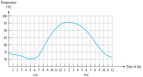
FIGURE 1–1 Graph of an analog quantity (temperature versus time)
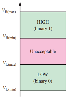
FIGURE 1–2 Logic level ranges of voltage for a digital circuit
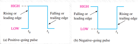
FIGURE 1–3 Ideal pulses
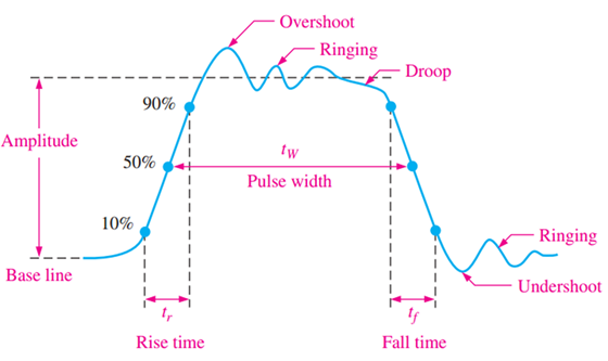
FIGURE 1–4 Nonideal pulse characteristics
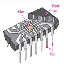
FIGURE 1–5 Cutaway view of one type of fixed-function IC package (dual in-linepackage) showing the chip mounted inside, with connections to input and output pins
-1.1 Structure and Methods
-1.2 Introductory
-Chapter1 Introductory Concepts
-Test1
-2.1 Number Systems
-2.2 Codes
-Chapter2 Number systems and Codes
-Test2
-3.1 Logic Gates(1)
-3.2 Logic Gates(2)
-Test3
-4.1 Boolean Algebra
-4.2 Logic Simplification
-Chapter4 Boolean Algebra and Logic Simplification
-Test4
-5.1 Analysis of combination logic circuit
--5-1 Analysis of combination logic circuit
-5.2 Design of combination logic circuit
--5-2 Design of combination logic circuit
-5.3 Half and Full Adders
-5.4 Encoders
-5.5.1 Decoders(1)
-5.5.2 Decoders(2)
-5.5.3 Decoders(3)
-5.5.4 Decoders(4)
-5.6.1 Multiplexers (Data Selectors)(1)
--5-6 Multiplexers (Data Selectors)(1)
-5.6.2 Multiplexers (Data Selectors)(2)
--5-6 Multiplexers (Data Selectors)(2)
-5.7 Comparators
-Chapter5 Combinational Logic Circuit
-Test5
-6.1 Latches
-6.2 Flip-Flops
-6.3 Flip-Flops Applications
-Test6
-7.1 Analysis of Sequential logic circuit-1
--7–1 Analysis of Sequential logic circuit-1
-7.2 Analysis of Sequential logic circuit-2
--7–2 Analysis of Sequential logic circuit-2
-7.3 Design of Sequential logic circuit-1
--7.3 Design of Sequential logic circuit-1
-7.4 Design of Sequential logic circuit-2
--7-4 Design of Sequential logic circuit-2
-7.5 Counters-1
-7.6 Counters-2
-7.7 Registers-1
-7.8 Registers-2
-Chapter7 Sequential Logic Circuit
-Test7
-8.1 555 Timer circuit structure and working principle
--8.1 555 Timer circuit structure and working principle
-8.2 Application circuit of 555 Timer
--8.2 Application circuit of 555 Timer
-Chapter8 Generation and Shaping of Pulse Signal
-Test8